




Kubota 05 Series Specifications and Torque Settings (D905 through V1505)
Looking for the Kubota 05 series specifications and torque settings? On this page you'll find everything at a glance: the technical data per model, the common engine characteristics, and the complete torque table from the workshop manual. Whether you're replacing a head gasket, removing an injector, or reassembling the cylinder head, below you'll tighten every bolt to the correct torque.
Suitable for the entire series: D905, D1005, D1105, D1305, V1205, V1305 and V1505 (incl. turbo -T/-TE and versions -E/-E2B/-E3B/-E4B).
Kubota 05 series technical specifications per model
The seven base models share much of the same technology, but differ in bore, stroke, and displacement. The power figures below are the intermittent values at 3000 rpm.
| Model | Cylinders | Bore × stroke | Displacement | Power (intermittent @3000) |
|---|---|---|---|---|
| D905 | 3 | 72 × 73.6 mm | 898 cm³ | 14.9 kW / 20 hp |
| D1005 | 3 | 76 × 73.6 mm | 1001 cm³ | 16.8 kW / 22.5 hp |
| D1105 | 3 | 78 × 78.4 mm | 1123 cm³ | 18.7 kW / 25 hp |
| D1305 | 3 | — | 1261 cm³ | 21.0 kW / 28 hp |
| V1205 | 4 | 72 × 73.6 mm | 1198 cm³ | 20.1 kW / 27 hp |
| V1305 | 4 | 76 × 73.6 mm | 1335 cm³ | 22.4 kW / 30 hp |
| V1505 | 4 | 78 × 78.4 mm | 1498 cm³ | 25.0 kW / 33.5 hp |
Kubota 05 series common characteristics
Despite the differences in cylinder count and displacement, the engines are technically closely related. They have the following in common:
| Type | Water-cooled, 4-stroke, indirect injection (E-TVCS, spherical swirl chamber) |
| Compression ratio | 23:1 (turbo 22.5:1) |
| Rotation direction | Counterclockwise (viewed from the flywheel) |
| Firing order | 3-cylinder 1-2-3; 4-cylinder 1-3-4-2 |
| Idle speed | 800–950 rpm |
| Injection pump | Bosch MD mini-pump |
| Injection pressure | 13.73 MPa (140 kgf/cm², 1991 psi) |
| Injection timing | 19° before TDC (some 3600 rpm versions 22°) |
| Starter motor | 12 V, 1.0–1.2 kW |
| Alternator | 12 V, 360 W |
| Battery | 12 V, 65–70 Ah |
| Cold start aid | Glow plug in the swirl chamber |
| Valve clearance (cold) | 0.145–0.185 mm |
Kubota 05 series torque settings: the complete table
The torque values below come from the workshop manual. An "*" means you apply engine oil to the thread and seating surface before tightening. The general values apply to bolts for which no specific torque is given; always use the specific torque when one exists.
| General (standard bolt / special bolt) | Torque |
|---|---|
| M6 | 7.9–9.3 / 9.81–11.2 N·m |
| M8 | 18–20 / 24–27 N·m |
| M10 | 40–45 / 49–55 N·m |
| M12 | 63–72 / 78–90 N·m |
| Specific part | Torque |
|---|---|
| Cylinder head bolt M10×1.25 (engine oil on thread, in sequence, in stages) | 64–68 N·m (6.5–7.0 kgf·m) |
| Valve cover bolt M7×1.0 | 7–8 N·m |
| Valve cover bolt M6×1.0 | 9.81–11.2 N·m |
| * Main bearing bolt 1 M8×1.25 | 30–34 N·m |
| * Main bearing bolt 2 M9×1.25 | 49–53 N·m |
| * Flywheel bolt M10×1.25 | 54–58 N·m |
| * Connecting rod bolt M8×1.0 | 42–46 N·m |
| * Rocker arm bracket nut/bolt M7×1.0 | 22–26 N·m |
| * Idler gear shaft bolt M6×1.0 | 9.81–11.2 N·m |
| * Fan pulley bolt M14×1.5 | 236–245 N·m |
| Glow plug M8×1.0 | 7.9–14 N·m |
| Injector holder complete M20×1.5 | 49–68 N·m |
| Injector holder | 35–39 N·m |
| Injection pipe retaining nut M12×1.5 | 25–34 N·m |
| Overflow pipe retaining nut M12×1.5 | 20–24 N·m |
| Oil drain plug copper M12×1.25 | 33–37 N·m |
| Oil drain plug rubber coated M22×1.5 | 45–53 N·m |
| Bearing case cover bolt M6×1.0 | 9.81–11.2 N·m |
| Oil pressure sensor PT 1/8 | 15–19 N·m (1.5–2.0 kgf·m) |
| Starter motor B-terminal nut M8 | 5.88–11.8 N·m |
| Alternator pulley nut | 58.4–78.9 N·m |
Tightening the Kubota 05 series cylinder head bolts
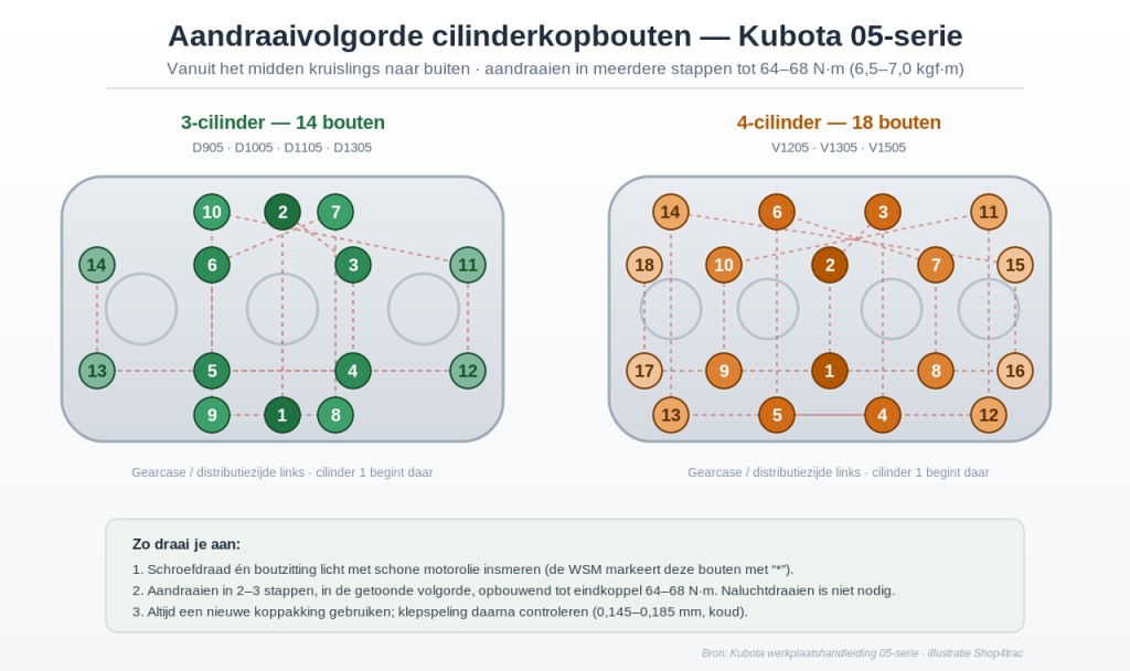
The cylinder head is the most critical tightening job on these engines. Do it carefully, as an incorrectly tightened head is one of the main causes of head gasket leaks. The rules:
- Apply engine oil to the thread of each head bolt before tightening.
- Tighten in multiple stages, not to final torque in one go.
- Work from the center outward in a crisscross pattern following the prescribed sequence (14 bolts in sequence for a 3-cylinder, 18 bolts for a 4-cylinder).
- Final torque: 64–68 N·m (6.5–7.0 kgf·m).
- Always use a new head gasket.
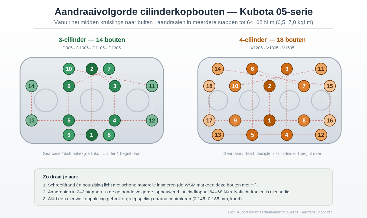
Tightening sequence of the cylinder head bolts: from the center outward in a crisscross pattern, in multiple stages up to 64–68 N·m.
Good news for maintenance: with this series the cylinder head bolts do not need to be re-torqued and the valve clearance does not need to be readjusted after the engine has warmed up. Set the valve clearance cold to 0.145–0.185 mm and you're done.
Tip from our workshop: if you're removing the head, order a new gasket or head set right away. Never reuse an old head gasket, and make sure the pin-pipe isn't installed upside down and that no O-ring is fitted on it.
- Head set/gasket set V1505 (VAR-0174, €79.50): view the V1505 head set
- Head set/gasket set D1105/D1305 (VAR-0181, €59.50): view the D1105/D1305 head set
- Complete cylinder head V1505 (SKU-990026, €695, was €945): view the complete V1505 head
- Complete cylinder head D1105 (SKU-990021, €795.50): view the complete D1105 head